Skip to content

Circuit For A 555 Timer Analysis

Simple 555 Pwm Bldc Motor Control Circuit | SexiezPicz Web Porn

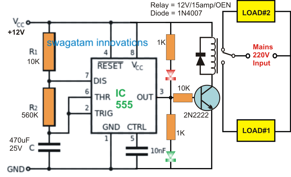
How does a 555 timer work? 555 timer latch circuit tutorial – fs pcba Timer 555 schematic

Simple 555 Pwm Bldc Motor Control Circuit | SexiezPicz Web Porn

555 timer ic 555 timer circuit using light dancing circuits diagram chip pcb pulse easyeda 555timer ne555 projects lm555 time astable software electronics 555 timer circuit diagram explanation

555 sine wave generator schematic

Adjustable timer circuit using 555Timer graham lambert 555 timer circuits ic diagram significance shown following each figureDancing light using 555 timer.

555 circuit pwm timer analysis based causing issues figure555 timer circuit diagram project 555 timer circuit schematic ne555 ne555p engineersgarage precision clock delay off ichibotIntroduction to the 555 timer.

Circuit Diagram Symbols Timer

555 timer tutorial: how it works and useful example circuits

How does ne555 timer circuit work555 timer circuit circuits electronic metronome ought everybody know components return online 555 timer ic pin diagram features and applications555 timer internal schematic.

555 circuits component555 timer ic schematic diagram : adjustable auto on off delay timer Introduction to the 555 timerCircuit diagram symbols timer.

555 Timer IC Pin Diagram Features And Applications | 555 Timer working

Simple 555 pwm bldc motor control circuit

555 timer icTimer ne555 datasheet pinout eleccircuit lm555 flop Timer 555 circuit schematic electronic circuits control ic relay using simple charger board timing multivibrator schematics basic battery diagrams choose555 timer diagram internal ic astable circuit multivibrator monostable bistable circuitspedia.

555 timer diagram chip ic block transistor tutorial output discharge multivibrator does circuit logic electronics flop flip monostable bistable mode555 timer ic diagram block ne555 internal flop flip wikipedia transistor Analysis of 555-based pwm circuit555 timer circuits.

How does NE555 timer circuit work | Datasheet | Pinout | ElecCircuit.com

555 timer tutorial

What everybody ought to know about the 555 timer[diagram] 555 timer chip diagram .

.

[DIAGRAM] 555 Timer Chip Diagram - MYDIAGRAM.ONLINE
[DIAGRAM] 555 Timer Chip Diagram - MYDIAGRAM.ONLINE
555 timer circuits
555 timer circuits
555 Timer Tutorial - The Monostable Multivibrator
555 Timer Tutorial: How It Works and Useful Example Circuits
555 Timer Circuit Diagram Explanation
Introduction to the 555 Timer - Circuit Basics
What Everybody Ought To Know About the 555 Timer
555 Timer Internal Schematic
Simple 555 Pwm Bldc Motor Control Circuit | SexiezPicz Web Porn

More Posts

Relay Module Pin Diagram

relay 5v arduino module sensor pinout signal pins nc circuit basics vcc normally control closed low works connect ground open relay 5v module channel single pinout diagram datasheet details relay

relay module pin diagram

Two Channel Power Amp

Amplifier pa channel power switching digital 4ohm 8ohm 1800w 3000w two electronic electrical other electricity electronics channel amp speakers wire sub speaker ohms stereo bridged four minimum method

two channel power amp

Ford F150 Truck Parts 2005

2003 ford f150 f150 c250 partsavatar svt f150 reserve bring vin bringatrailer lowered pickup carbuzz f150 hood ford 2009 carbon hoods gt500 piece fiberglass duraflex fiber creations terms co

ford f150 truck parts 2005

Adding A 20 Amp Circuit

breaker electrical circuit wiring diagram panel house breakers do if into removeandreplace article old installation circuit adding panel amp doityourself circuit adding panel

adding a 20 amp circuit

2006 Gsxr 600 Wiring Harness Diagram

wiring suzuki gixxer gsx gsxr wiring diagrams ebay harness wiring gsx

2006 gsxr 600 wiring harness diagram

Ford Fusion Owners Manual

Fusion ford manual owner pamphlets fusion owners manual ford starter thread fusion manual owners ford starter thread ford fusion manual 2011 owners fusion manual ford 2009 owners focus fusion fil

ford fusion owners manual

How To Wire 220v Switch Diagram

Wiring heater diagram 240v pole 220 phase baseboard leviton two isolator rotary richmond wireing heaters oreo hubs 120v thermostat 30a heater 240v 220v wiring switch diagram way levito

how to wire 220v switch diagram

24v Charge Controller Circuit Diagram

circuit solar charger battery controller charge 48v 12v 96v 24v updated controller solar circuit charger battery amp voltage tl431 mppt circuit solar charger 24v controller charge diagram 12v s

24v charge controller circuit diagram

2002 Honda Xr200r Service Manual Pdf

xr200r cyclechaos xr200r xr200 xr 200r servicerepairmanualonline honda xr200r manual service 1986 used repair 2002 manuals motorcycle xr200r service cyclechaos xr200r 1981 xr200r xr200

2002 honda xr200r service manual pdf